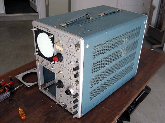
Fig. 1 Knobs have been pulled for cleaning. Unfortunately all the tubes were pulled from the inside.
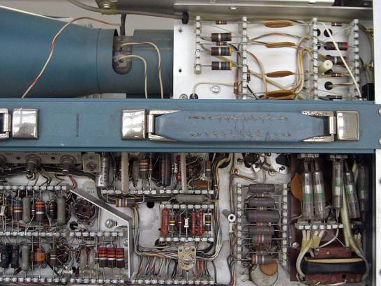
Fig. 2 The High Voltage section looks very clean. The only dust seems to have settled on top of the components.
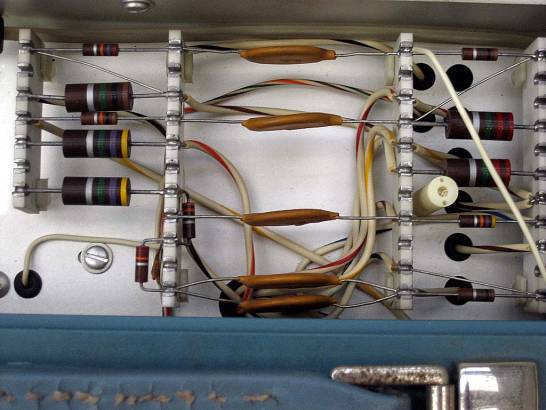
Fig. 3 No black soot from long hours of use.
With all the parts re-installed it was time to see what worked and what didn’t. After checking the solid-state diodes and capacitors for shorts and opens with an ohmmeter I applied power to the scope. After the 30 seconds the bimetal timing relay clicked. My first step was to check the low voltage supplies. The –150 volt rail was low at –145 volts, but was easily tuned to the correct voltage. From there the remaining supply voltages all seemed to be within 2% of the specified value detailed in the manual. At this point I heard no crackling of high voltage when the relay engaged, and indeed there was no glow from the 5642 diodes. I found that the 12AU7 feedback amplifier was dark and cold to the touch. Slipping the tube out of the socket so the HV oscillator could run open loop caused all of the 5642 rectifiers to glow brightly. At first what appeared to be an open filament on the 12AU7 turned out to be a bad connection on the tube and socket. Wiggling the tube in the socket caused the HV supply to come to life and into regulation. I still had no trace, but the scope was starting to come alive bit by bit. I next turned my attention to the horizontal amplifier. I had the horizontal amplifier switched to external with no signal. In this state the left neon bulb used for horizontal beam centering was lit up while the right side was dark. It was no surprise when I found one of the tapped plate load resistors running very hot and it’s sibling running very cold. Again this was tracked down to a tube socket issue. With two instances of this, I concluded that I should clean all of the tube pins by wiping them with a linen wipe soaked with contact cleaner. I then reinserted the tubes one by one gently rocking them in the tube socket before seating them. When this was done the scope truly started to breathe again.
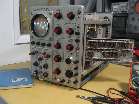
Fig. 4 Looks good but…
What you can’t see in this picture is a high frequency ripple imposed on the sin wave. I suspect the ripple comes from the 60 Khz Hartely oscillator in the high voltage supply. I’m going to forgo tracking this down until I get my high voltage probe out and confirm that the regulation is correct on that supply. I will want to verify that it is the same frequency as the HV oscillator. I also need to go in and confirm that the ripple on the low voltage supplies is within in specification as well. After this is done the real work of getting the time base and delayed sweep working can begin.
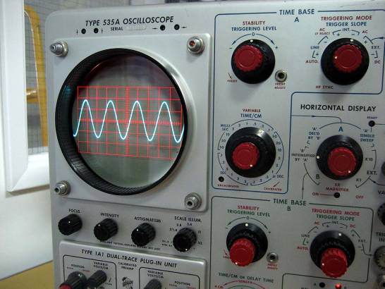
Fig. 5 This closer shot shows the ripple
One of the great things about this particular scope is the shear number of tubes and the ingenious construction to accommodate them. When it’s up and running it is truly a beautiful piece of industrial art.
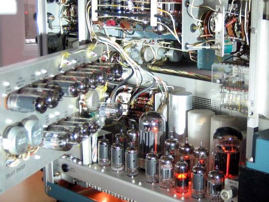
Fig. 6 Tubes inside the Scope
When I got home tonight I set about setting the HV supply to the correct value and confirming if the high frequency ripple imposed on waveforms was from the HV Oscillator. I needed a simple way to phase lock the ripple to the displayed waveform on the 535A. Using my 547 I measured the plate of the HV Hartley oscillator. I triggered the 547 on timebase A so that I could redisplay the sweep output on the 535A. Here is a block diagram of my setup.
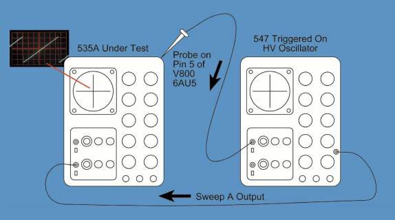
Fig. 7 Block Diagram of Test Setup
Using this setup I could see that the ripple was indeed locked to the 547, which was triggered by the 535A HV oscillator. Unhooking the probe caused the ripple to appear as a blurred trace. Locking the ripple to the waveform also allowed me to see that the ripple was predominately in the horizontal amplifier as indicated by the back and forth movement of the high frequency sin wave. The horizontal amplifier is in very close proximity to the HV oscillator at the top of the scope. Hmmm…. I then went up stairs and found Dave’s post, “Once you put the shield back in place over the 5642's, your high-frequency ripple will go away. The oscillator puts out a strong EM field.” Went back down stairs, replaced the shield and problem solved. Thanks Dave. I think I will take his advice about the capacitors.
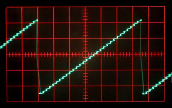
Fig. 8 Showing the Ripple in Step With the Sweep
At this point nearly everything is working on the scope. The only exception was the ‘A’ DEL’D BY ‘B’ and the ‘B’ INTENSIFIED BY ‘A’ did not work. I started by reviewing the circuit description of the Delay Pickoff Circuit on page 4-7 of the manual. Operation of the circuit seemed pretty straightforward. A differential amp was created with two 6AU6 tubes for the inputs and ½ of a 6DJ8 as a current source. This dif amp is used as a comparator with the compare point set by a voltage divider consisting of three pots. Two pots set the upper and lower limit of the delay pickoff timing, while the wiper of the ten-turn pot feeds one input of the amp. The other input of the amp is fed by either the ‘A’ or ‘B’ Time base, depending on the front panel settings of the horizontal display switch. Varying the trigger point with the ten-turn pot should vary the duty cycle of the amplifier output. This output is then fed into a multivibrator, read flip-flop, which produces nice square edges on the waveform. A simple RC differentiator feeds an output amplifier that passes only the positive going edges. When I looked at the output of V424 I saw the expected waveform. What surprised me was that the duty cycle did not change with the adjustment of the ten-turn delay pot. After confirming that the saw tooth waveforms from the time bases appeared on the grid of V414 I turned my attention to the grid of V424. No change in the DC voltage when I adjusted the delay pot. Un-soldering and checking with an ohmmeter revealed a ten-turn pot with one open leg. Luckily, the parts bin had a replacement 30K ten-turn pot. Here is the simplified schematic from the circuit description section of the manual.
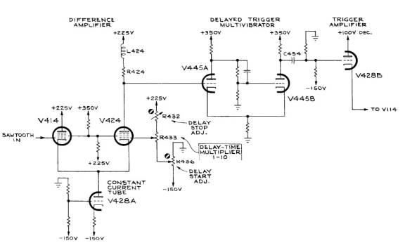
Fig. 9 Schematic of Triggered Sweep
Here you can see the ’B’ intensified by ‘A’ is working nicely. The 547 on the right is monitoring the output of the multivibrator. As the ten turn pot is adjusted to move the intensified portion of the waveform across the screen the duty cycle of the multivibrator changes. If you look closely the removed bad ten-turn potentiometer is sitting next to the role of solder.
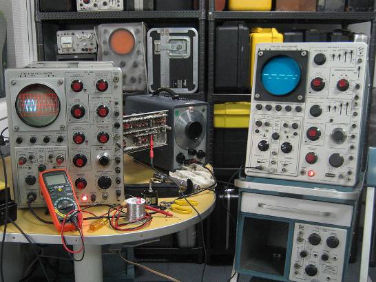
Fig. 10 Checking the output of the multivibrator
With the scope working I could now begin the process of calibration. The power supplies and Calibrator were easy enough to set using the procedure in the manual. As with any piece of older gear the alignment procedures sometimes reference test gear that is no longer available. Such was the case in the procedure for setting the geometry. The manual described a procedure using a Tektronix 180A. I had never heard of this piece of test gear, so I downloaded the manual from the BAMA archive.
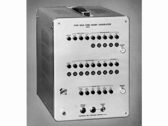
Fig. 11 Tektronix 180A
Reading the 180A manual told me that the time mark outputs of the 180A generator were exponential pulses. My Tektronix AFG 3021 would be a good substitute for the 180A. I was able to make the same settings and duplicate the procedure exactly.

Fig. 12 Tektronix AFG 3021 Connected to the Scope
Here is the resultant waveform using the procedure described in the Tektronix 535A manual
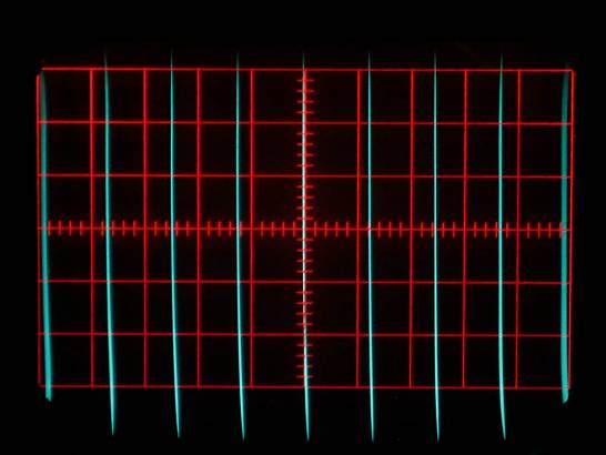
Fig. 13 Screen Shot of Geometry Check
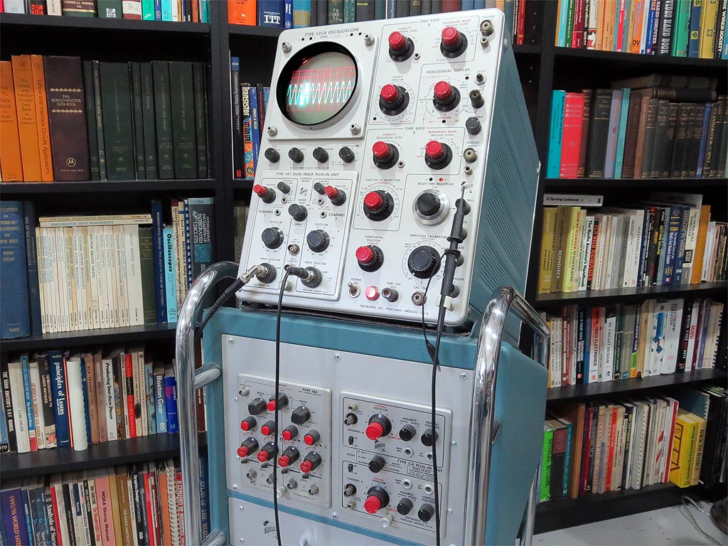
Fig. 14 Tektronix 535A Ready for Service