Drag mouse with shift pressed to zoom
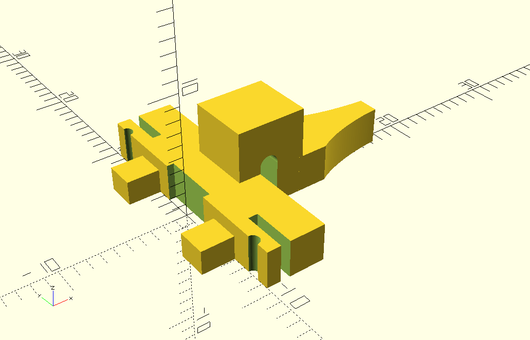
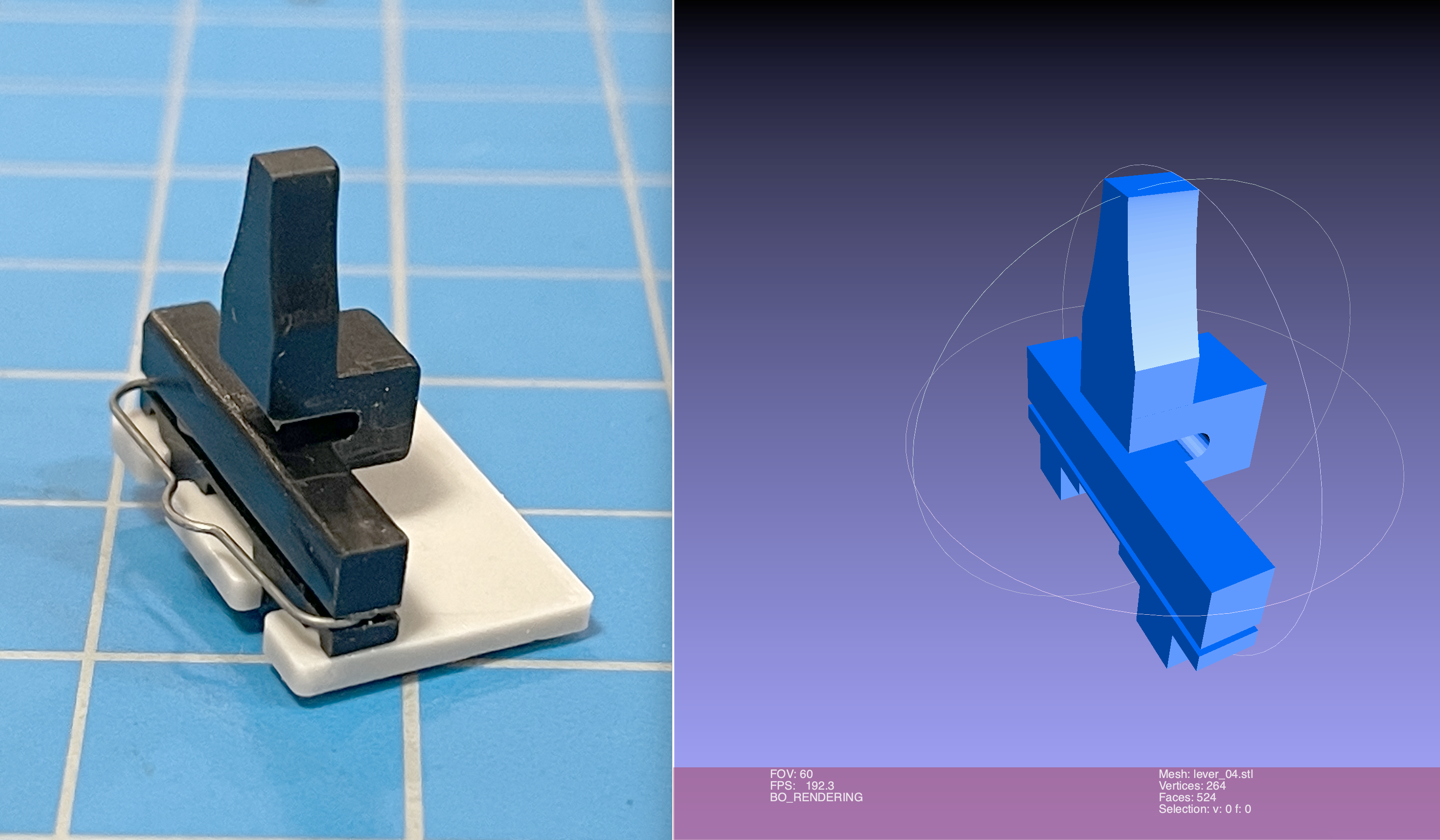
3D rendering of STL File Using JSC3d
//
//Switch lever used on HP equipment.
//

/*
Changes from hp_lever-2.2.scad to hp_lever-2.4.scad
    Increased size of notched cube by .6mm in x (50 to 56)
    Translated notched cube -.4mm in x (33 to 29)
    Translated notch cylinder -.3mm in x (57,5 to 54.5)
    Translated notch cube -.3mm in x (50 to 47)
    Decreased size of main body cube by .3mm (50 to 47)
    Increased size of spring notch by .05mm (7 to 7.5, 3 cubes)
    Changed SVG lever_06.svg to lever_07.svg (improved curve)
*/

// Set Viewport
$vpr = [55, 0, 323];
$vpt = [10, 4, -2.5];
$vpd = 70;

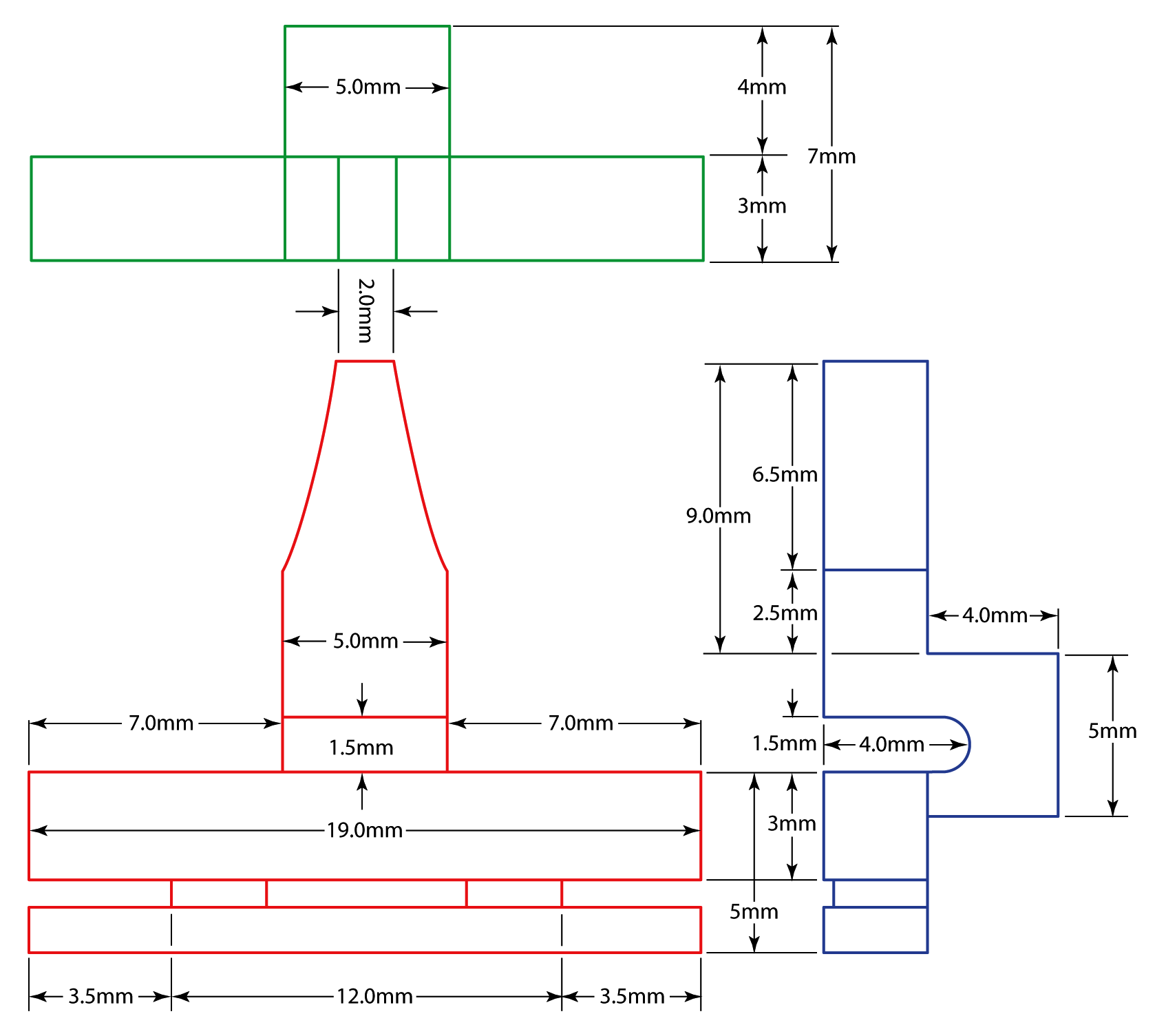
//Scale by 1/10
scale([.1,.1,.1]){
//Merge geormetries
    union(){
//Import and extrude SVG geometry for lever
        translate([82, -25, 15]){
            linear_extrude(height = 30, center = true, scale=1) {
                import(file = "lever_07.svg", center = false, dpi = 96);
            }
        }
 //Notched cube
        difference(){
            translate([29, -25, 0]){
                cube([56,50,70]);
            }
            rotate([90,0,0]){
                translate([54.5, 35, -26]){
                    cylinder(52,7.5,7.5, $fn=100);
                }
            }
            translate([47, -26, -1]){
                cube([15,52,35]);
            }
        }

///////////////-Subtracted Geometries-///////////////

//Main body and spring holder
        difference(){
            translate([0, -95, 0]){
                cube([47,190,30]);
            }
            translate([11, -96, -1]){
                cube([7.5,36,32]);
            }
            translate([11, 61, -1]){
                cube([7.5,36,32]);
            }
            translate([11, -95, -.1]){
                cube([7.5,190,15 ]);
            }
            translate([-3, -23, -1]){
                cube([8.5,46,32]);
            }
//End Notchs
            translate([-.5,80,-1]){
                cylinder(r1=5, r2=5, h=32, center=false, $fn=100);
            }
            translate([0,-80,-1]){
                cylinder(r1=5, r2=5, h=32, center=false, $fn=100);
            }
        }
 /////////////-End Subtracted Geometries-/////////////

//Mounting tabs
             translate([-13, (35.5+11.85), 9.75]){
                cube([26.5,23.7,19.5], center=true);
            }
             translate([-13, -1*(35.5+11.85), 9.75]){
                cube([26.5,23.7,19.5], center=true);
            }
//Center Support
            translate([9, -4.5, 0]){
                cube([26,9,30]);
            }
    }
}
Open SCAD Code
<?xml version="1.0" encoding="UTF-8" standalone="no"?>
<!-- Created with Inkscape (http://www.inkscape.org/) -->
<svg
   width="210mm"
   height="297mm"
   viewBox="0 0 210 297"
   version="1.1"
   id="svg12"
   inkscape:version="1.1 (c4e8f9e, 2021-05-24)"
   sodipodi:docname="lever_05.svg"
   xmlns:inkscape="http://www.inkscape.org/namespaces/inkscape"
   xmlns:sodipodi="http://sodipodi.sourceforge.net/DTD/sodipodi-0.dtd"
   xmlns="http://www.w3.org/2000/svg"
   xmlns:svg="http://www.w3.org/2000/svg">
  <sodipodi:namedview
     id="namedview14"
     pagecolor="#ffffff"
     bordercolor="#666666"
     borderopacity="1.0"
     inkscape:pageshadow="2"
     inkscape:pageopacity="0.0"
     inkscape:pagecheckerboard="0"
     inkscape:document-units="mm"
     showgrid="false"
     showguides="false"
     inkscape:zoom="3.3602084"
     inkscape:cx="170.07874"
     inkscape:cy="1075.8261"
     inkscape:window-width="1312"
     inkscape:window-height="936"
     inkscape:window-x="62"
     inkscape:window-y="29"
     inkscape:window-maximized="0"
     inkscape:current-layer="layer1" />
  <defs
     id="defs9" />
  <g
     inkscape:label="Layer 1"
     inkscape:groupmode="layer"
     id="layer1">
    <path
       fill="#f8da2d"
       d="M 25.00236,297.04 H 0 v -50 h 25.00236
       c 0,0 11.685749,4.95901 32.498645,9.97199
       20.812893,5.01298 32.498993,5.02816 32.498993,5.02816
       v 20.00077 c 0,0 -12.15564,0.43744 -32.498993,5.0278
       C 37.157649,291.65907 25.00236,297.04 25.00236,297.04 Z"
       id="path73"
       style="stroke-width:0.352773" />
  </g>
</svg>
Inkscape SVG XML
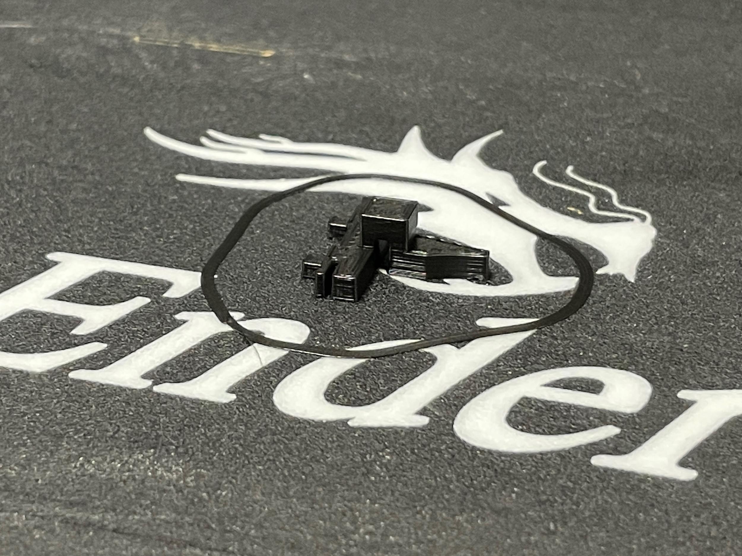
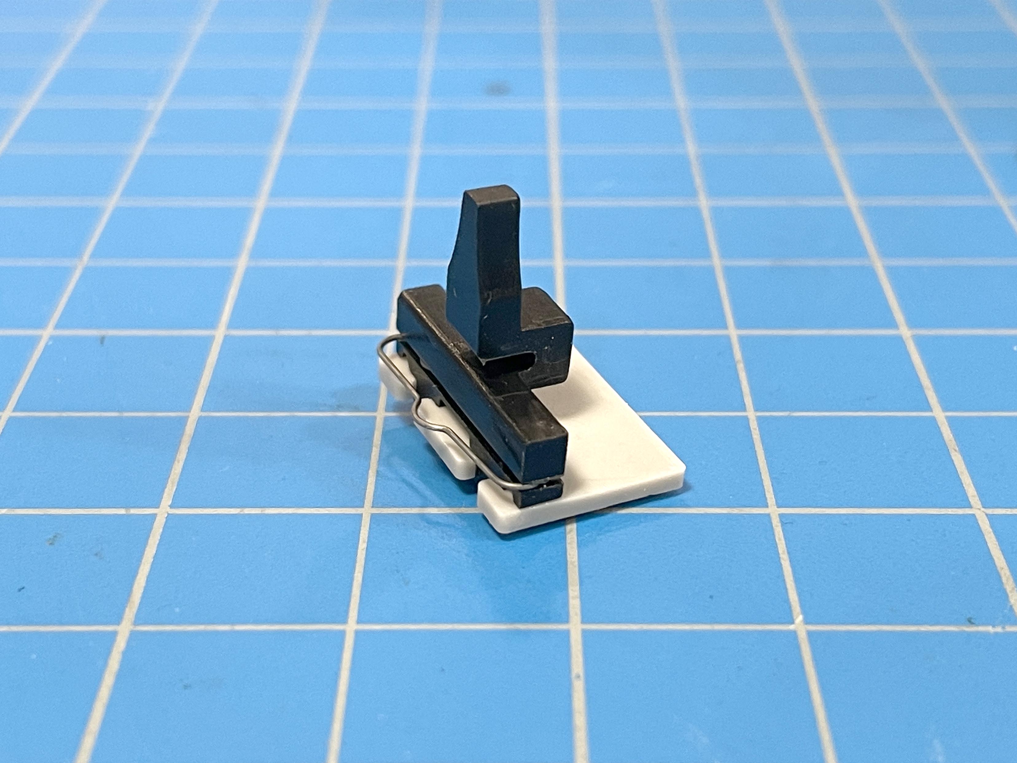
Freshly Printed Part
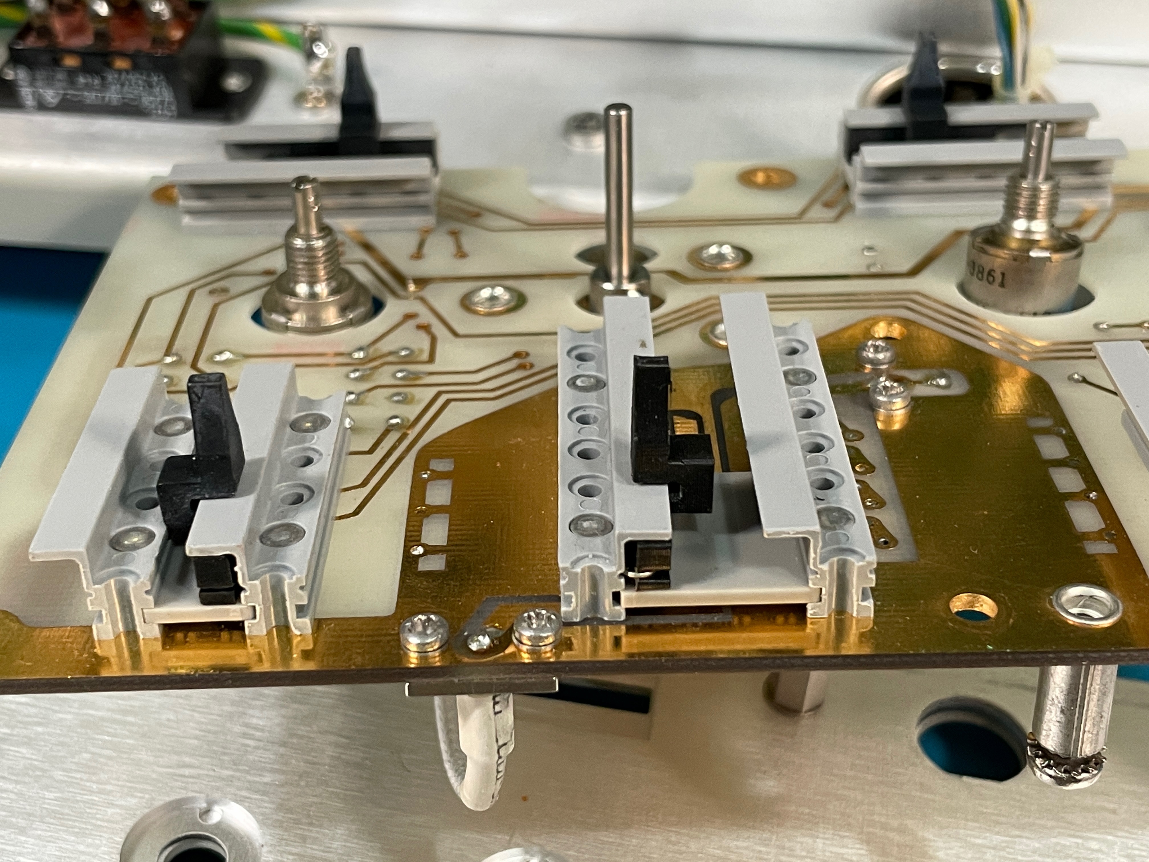
Lever Installed on Board
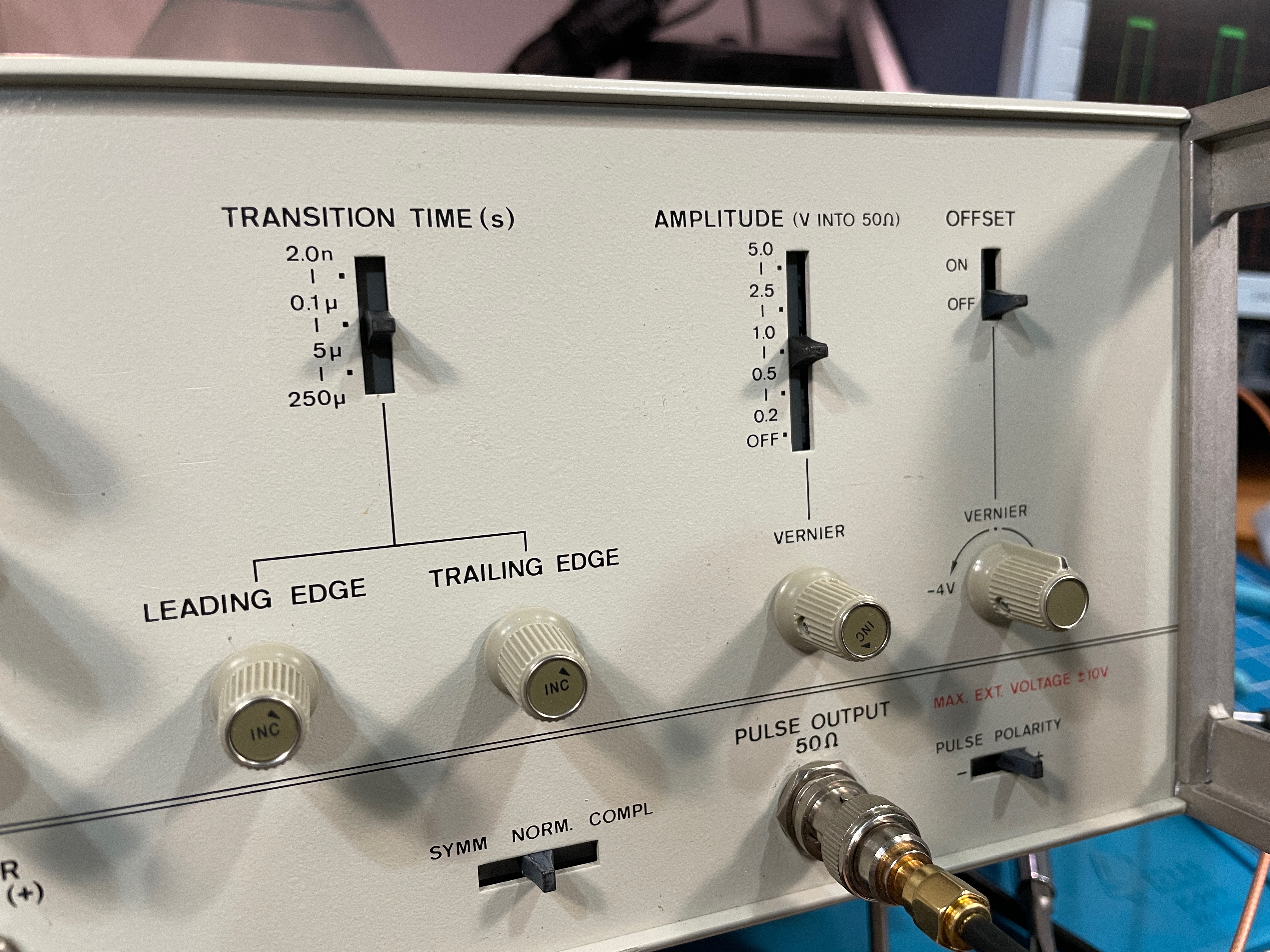
Repaired Amplitude Control
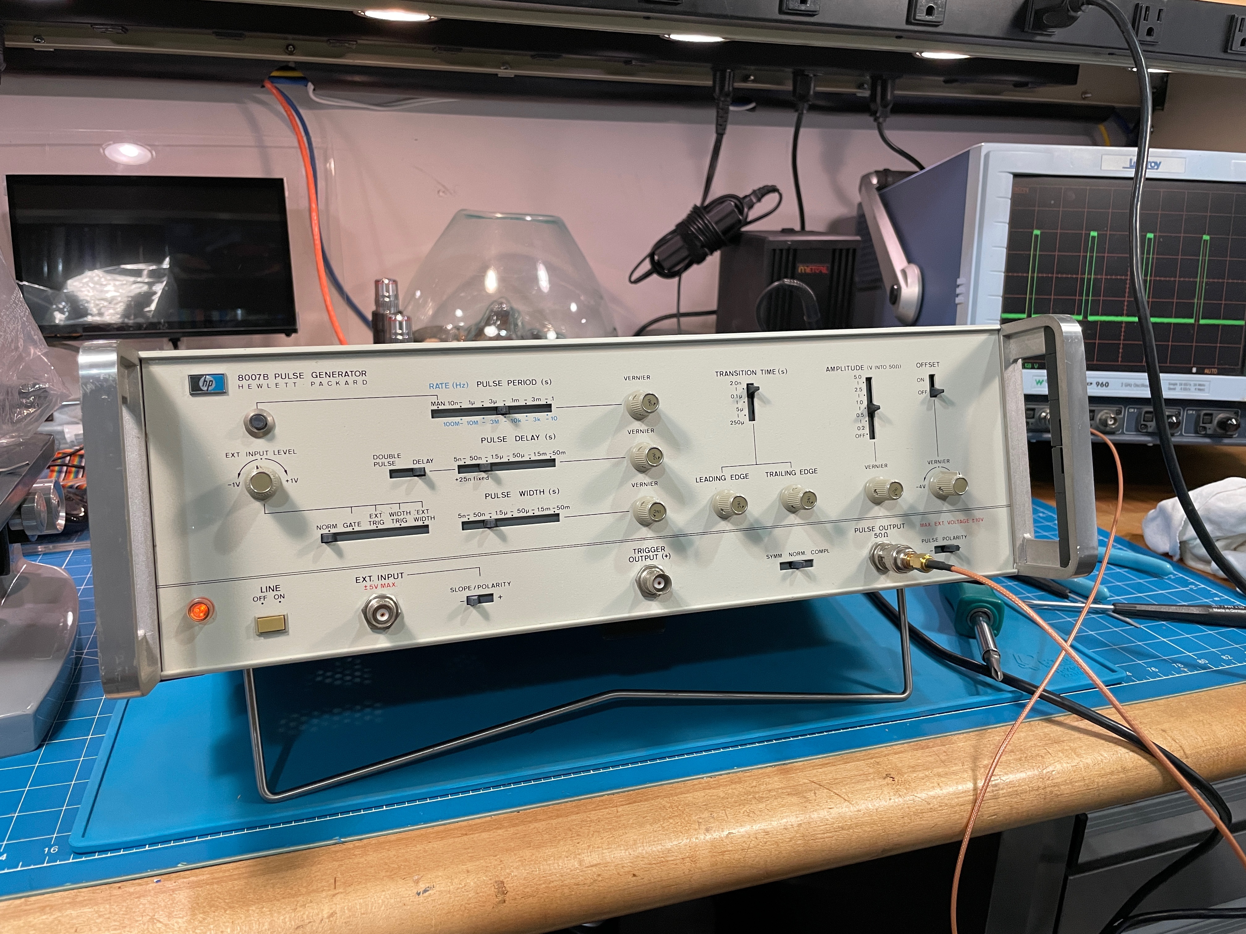
Working HP 8007B
Download STL
Download SVG File
Download SCAD File

|

|
|
Home |
Return |
